Valves
A valve is a mechanical device used to control the flow of fluids (liquids, gases, or slurries) within a pipe or system.
Valves can either allow, stop, or regulate the flow of fluid through a passage by opening, closing, or partially obstructing the flow.
They are essential components in Various Systems, including Plumbing, Water treatment, Oil and Gas Pipelines, Chemical Processing, and HVAC (Heating, Ventilation, and Air Conditioning) systems.
The main functions of a valve
- Flow Control: one of the main functions of a valve is to regulate the flow of fluid through a pipeline or system. This can involve opening or closing the valve to increase or decrease the flow rate to meet the required demand. Valves can adjust the flow to a specific level, allowing for fine control over the rate at which the fluid moves through a system.
- Shut-off: valves can completely stop the flow of fluid in a pipeline or system. This shut-off capability is essential for isolating parts of a system for maintenance, repairs, or emergencies. Some valves (like gate or ball valves) are designed to either be fully open or fully closed, providing a clear on/off control to stop or start fluid flow.
- Pressure Control: valves can regulate the pressure within a system by controlling the flow of fluid. In pressure-controlled systems, valves can maintain a set pressure by modulating the flow to balance pressure levels. Some valves, such as relief or safety valves, are designed to open automatically to release excess pressure from a system, preventing damage or failure due to overpressure. Pressure-reducing valves (PRVs) can be used to decrease high pressure in a pipeline to a level that is safe or optimal for a particular system.
- Flow Direction Control: valves such as multi-port valves are used to direct fluid flow in different directions within a system. This is essential in systems where fluid must be routed to different locations depending on operational conditions. Check valves ensure that fluid flows only in one direction, preventing backflow and protecting the system from potential damage caused by reverse flow (e.g., preventing contamination or damage to pumps and other equipment).
- Safety Functions: valves such as pressure relief valves or safety valves are critical safety components in systems that involve pressurized fluids. They automatically release pressure when it exceeds a preset threshold to avoid system failure, explosions, or leaks. Some valves are designed to fail in a safe position (e.g., fully closed or fully open) in the event of a failure, ensuring that the system does not become unsafe or has a malfunction.
- Isolation and Shut-off for Maintenance: valves are used to isolate different parts of a system for routine maintenance or emergency shutdowns. By closing specific valves, sections of a system can be safely worked on without interrupting the entire operation.
- Blending Fluids: in some systems, valves are used to mix different fluids together. For example, in a mixing chamber, multiple flow streams are combined to create a desired mixture. This type of control is important in many chemical processes, HVAC systems, and water treatment facilities.
- Control of Fluid: while not common to all valves, some are designed to control temperature by managing the flow of heat transfer fluids, regulating the temperature in processes like cooling or heating systems.
Fosteel Srl has in stock an important range of valves, we kindly refer you to the information reported in each valve type.
ball valve
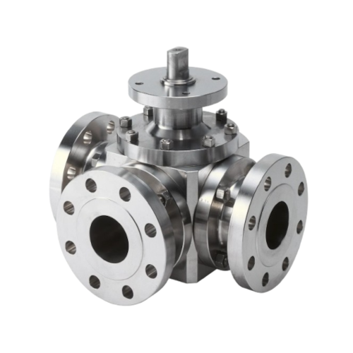
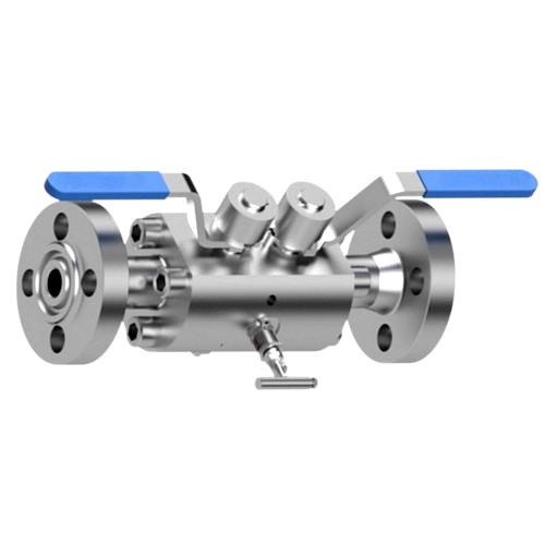
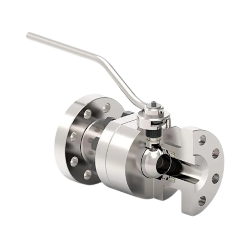
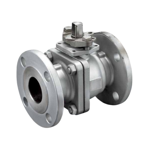
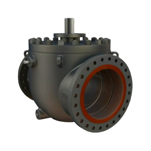
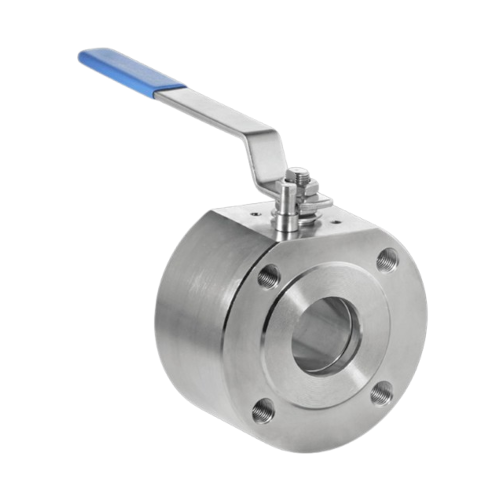
It’s a valve using a spherical ball with a hole (port) in the middle to control the flow of fluids. When it’s open, the hole in the ball aligns with the flow path, allowing fluid to pass through. When closed, the ball rotates so that the hole is perpendicular to the flow path, blocking the flow completely.
Ball valves are widely favored for their simplicity, reliability, and fast on/off control. They are ideal for systems that require quick shut-off and minimal maintenance. While they are excellent for fully opening or closing a flow, they are not suitable for precise flow control, as partial opening can lead to turbulence and inconsistent flow.
Key features of a Ball Valve
-
Operation: designed to provide quick on/off control. A handle or actuator is used to rotate the ball inside the valve body. A quarter-turn (90°) opens or closes the valve. In the open position, the hole in the ball aligns with the flow path; in the closed position, the ball blocks the flow.
-
Simple Design: with few moving parts, which makes them reliable and easy to operate.
-
Quick Acting: can be quickly opened or closed, making them ideal for applications that require fast shut-off.
Available Stock
-
Types: Monoblock, Split Body and Wafer types
-
Materials: Cast Iron, Brass, Bronze – Threaded and Flanged
-
Pressures & Sizes: From PN10 to PN64 and from DN15 to DN300
-
Materials: Carbon Steel and Stainless steel – Threaded, SW and Flanged
-
Pressures PN10, PN40 and PN64 / ANSI #150 – #300 – #600 – #800 – #1500 – #2500
- Sizes: from ½” to 8”
Common Applications
- Plumbing
- Chemical & Pharmaceutical
- Water Systems
- HVAC Systems
- Oil & Gas
- Food & Beverage
Types of Ball Valves
- Two Way Ball Valve
- Three Way Ball Valve
- Multi-Port Ball Valve
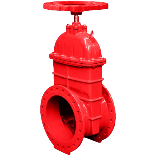
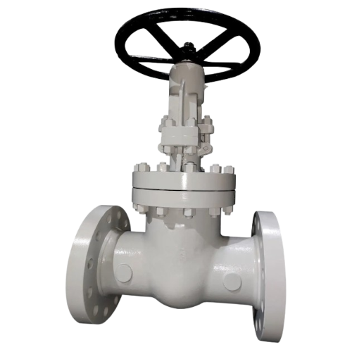
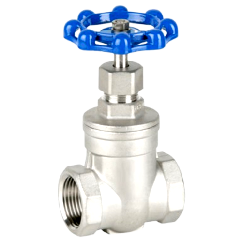
Gate Valve
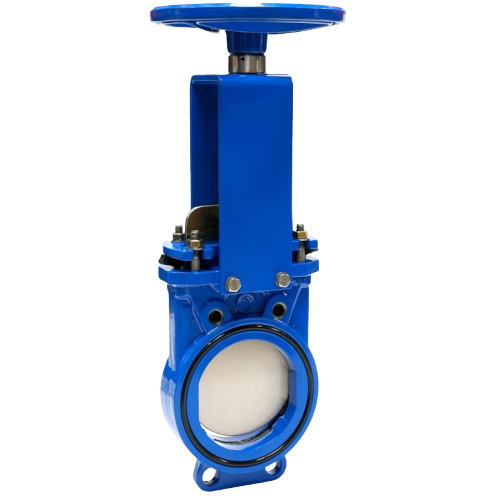
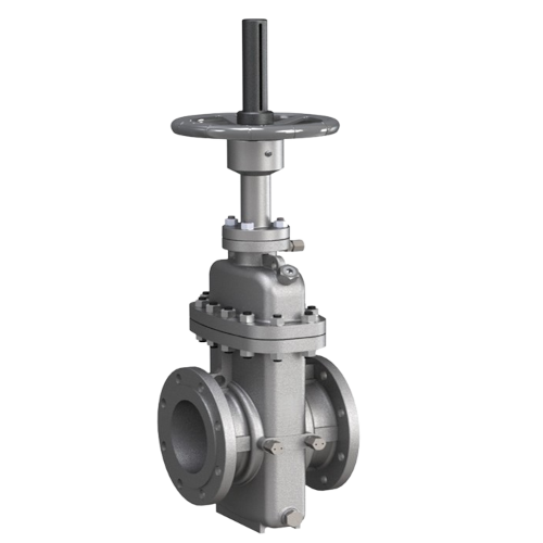
It’s a valve used to start or stop the flow of a fluid in a pipeline. It works by raising or lowering a straight or inclined (guillotine/plug) a wedge shaped (metal gate), into or out of the flow path. Gate valves are commonly used in situations where a fully open or fully closed valve is required, but they are not ideal for throttling or regulating flow.
Gate valves are designed for on/off control in systems that require minimal flow restriction when the valve is open. They are widely used in industries such as water treatment, oil and gas and chemical processing. However, they are not suitable for throttling or regulating flow, and their operation tends to be slower than other valve types.
Key features of a Gate Valve
-
Operation: has a threaded stem that moves the gate up or down as the valve handle is turned. When fully open, the gate is raised above the flow path, allowing the fluid to flow freely. When closed, the gate lowers and blocks the flow entirely.
-
Design: typically has a wedge or rectangular shape that fits into a seat, ensuring a tight seal when the valve is closed.
-
Full bore: typically has a “full bore” design, meaning the internal diameter of the valve is the same as the pipe’s, which allows for minimal flow restriction when the valve is fully open.
Available Stock
-
Types: Flat and Oval body with internal and external screw
-
Materials: Cast Iron – Threaded and Flanged
-
Pressures & Sizes: From PN10 to PN16 and from DN15 to DN600
-
Materials: Carbon Steel and Stainless steel – Threaded, SW and Flanged
-
Pressures: PN25, PN40 and PN64 / ANSI – #150 – #300 – #600 – #800 – #1500 – #2500
- Sizes: from ½” to 16”
Common Applications
- Water Systems
- Oil & Gas
- Fire Protection Systems
- Industrial Processes
Types of Gate Valves
- Wedge Gate Valve
- Parallel Gate Valve
- Knife Gate Valve
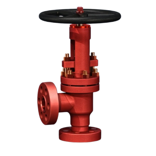
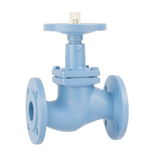
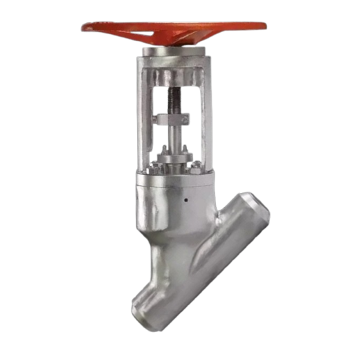
Globe Valve
It’s a valve commonly used to regulate the flow of fluids in a pipeline. Unlike ball or gate valves, which are typically used for on/off control, globe valves are designed to provide precise flow control. They are particularly useful in situations where flow needs to be adjusted or throttled.
While they are excellent for providing precise adjustments, they do introduce more pressure drop compared to other valve types, which must be considered when designing a system.
Key features of a Globe Valve
-
Operation: has a movable plug (disk) positioned inside the valve body. The plug is screwed into or out of the valve seat to control the flow. When open, the plug is lifted, allowing the fluid to pass through. When closed, the plug is lowered, sealing against the valve seat to stop the flow.
-
Design: has a spherical body with an internal baffle or partition that separates the inlet and outlet. The plug sits on top of this partition and can be adjusted to regulate the flow. The valve’s design creates a relatively high-pressure drop, which is why globe valves are better suited for flow regulation rather than on/off control.
-
Flow control: because the plug inside a globe valve moves along an axis perpendicular to the flow path, globe valves are better at throttling and controlling flow compared to ball and gate valves.
Available Stock
-
Types: with and without bellows
-
Materials: Cast Iron – Threaded and Flanged
-
Pressures & Sizes: From PN10 to PN16 and from DN15 to DN300
-
Materials: Carbon Steel and Stainless steel – Threaded, SW and Flanged
-
Pressures: PN25, PN40 and PN64 / ANSI #150 – #300 – #600 – #800 – #1500 – #2500
-
Sizes: from ½” to 16”
Common Applications
- Flow Regulation
- Oil & Gas
- Steam Systems
- Water Distribution
Types of Globe Valves
- Straight Pattern Globe Valve
- Angle Pattern Globe Valve
- Y-Pattern Globe Valve
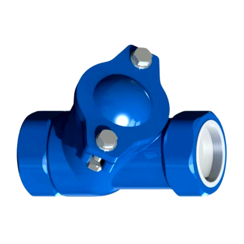
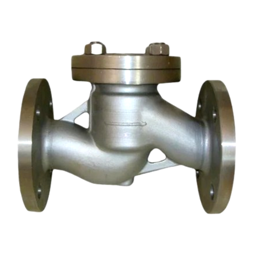
Check Valve
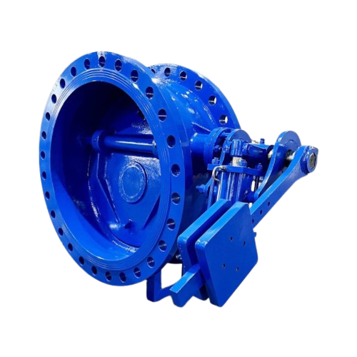
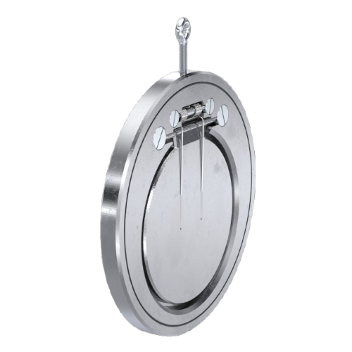
It’s valve that allows fluid to flow in only one direction and automatically prevents backflow (reverse flow) in a piping system. This makes it an essential component in many systems where preventing reverse flow is important for safety, efficiency, or protection of equipment.
Check valves are essential safety devices in many piping and fluid systems, ensuring that flow remains unidirectional and preventing backflow, which can cause damage or operational issues. They are available in various designs suited for different pressure, temperature, and application requirements, from simple ball check valves to more complex swing or spring-loaded versions.
Key features of a Check Valve
-
Automatic Operation: does not require manual intervention or a control mechanism to operate. They rely on the pressure of the flowing fluid to open the valve and a spring, gravity, or pressure difference to close it.
-
Direction Sentitive: only allows fluid to flow in one direction, and it automatically shuts when the flow reverses or stops.
-
Sealing Mechanism: inside there is usually a disk, ball, or other movable element that blocks the flow when the fluid attempts to reverse direction. The element is pushed open by the forward flow but closes when reverse flow is detected.
Available Stock
-
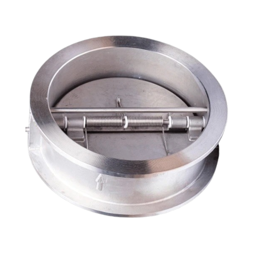
Types Swing Check, Ball Check, Piston Check normal face and Wafer version
-
Materials: Cast Iron – Threaded and Flanged
-
Pressures & Sizes: From PN10 to PN16 and from DN15 to DN600
-
Materials: Carbon Steel and Stainless steel – Threaded, SW and Flanged
-
Pressures PN25, PN40 and PN64 / ANSI #150 – #300 – #600 – #800 – #1500 – #2500
-
Sizes: from ½” to 16”
Common Applications
- Pumps & Piping Systems
- Water Supply Systems
- Oil & Gas
- Sewage & Wastewater Systems
- HVAC Systems
Types of Check Valves
- Swing Check Valve
- Ball Check Valve
- Lift Check Valve
- Spring Loaded Check Valve
- Dual Plate Check Valve
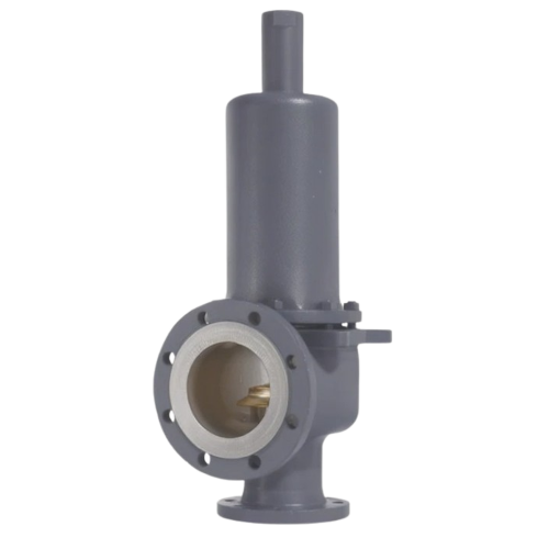
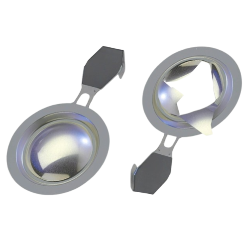
Pressure Relief Valve
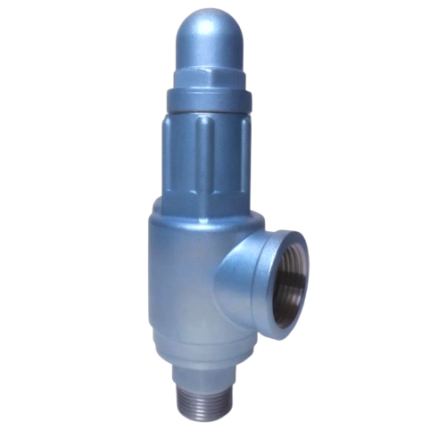
It’s a safety device designed to protect a system from excessive pressure by automatically releasing fluid (usually gas or liquid) when the pressure exceeds a predetermined limit. The primary function of a pressure relief valve is to maintain the pressure within a safe range to prevent damage to the system, equipment, or pipelines. It is commonly used in pressurized systems where overpressure can be hazardous.
A pressure relief valve is a critical component for maintaining safety in systems that operate under pressure. By automatically releasing excess pressure, it prevents damage to equipment and minimizes the risk of catastrophic failure. These valves are widely used in industries such as oil and gas, chemical processing, steam generation, water treatment, and HVAC systems to ensure the safe and efficient operation of pressurized systems.
Key features of a Pressure Relief Valve
-
Automatic Operation: automatically opens to release pressure when the system pressure exceeds the preset value. Once the pressure drops back within safe limits, the valve closes again.
-
Set Pressure: designed to open at a specific pressure, known as the “set pressure.” This pressure is typically adjustable based on the system’s needs.
-
Spring Mechanism: most pressure relief valves use a spring-loaded mechanism that holds the valve closed until the pressure exceeds the set value. When the pressure becomes too high, the spring compresses, causing the valve to open.
-
Seal: when the valve is closed, it forms a tight seal to prevent fluid from escaping. Once the pressure is relieved, the valve returns to its sealed position.
Common Applications
- Boilers
- Pressure Vessels
- Piping Systems
- Air Compressors
- HVAC Systems
- Hydraulic Systems
Types of Pressure Relief Valves
- Spring Loaded Pressure Relief Valve
- Pilot Operated Pressure Relief Valve
- Direct Operated Pressure Relief Valve
- Safety Relief Valve (SRV)
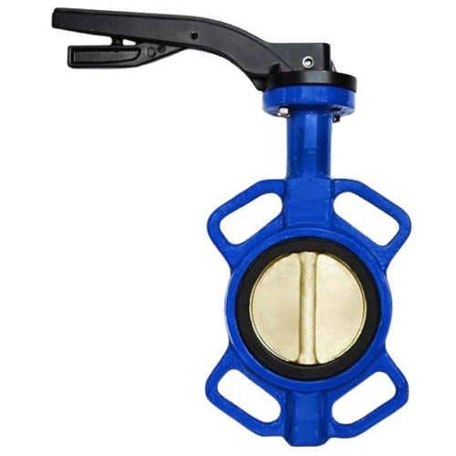
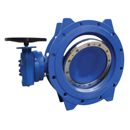
Butterfly Valve
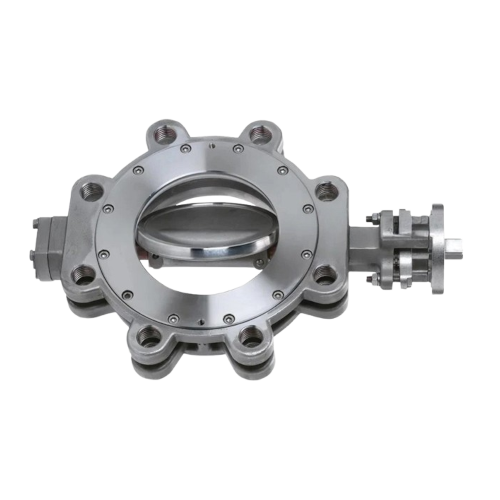
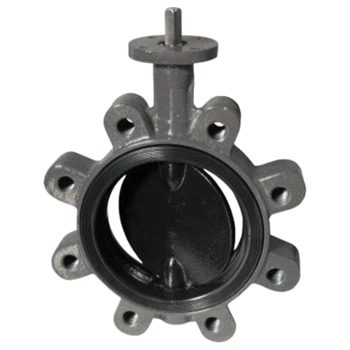
It’s a type of quarter-turn valve used to regulate, isolate, or control the flow of fluid in a pipeline. It uses a disk (“butterfly”) that rotates to open or close the valve, allowing the flow to pass through when the valve is open and stopping the flow when it is closed. The valve’s operation is simple and fast, and it is commonly used in various industries due to its lightweight design, reliability, and efficient flow control.
Butterfly valves are an excellent choice for applications where space, weight, and cost are important factors. They are well-suited for on/off control, as well as for moderate flow regulation in a variety of industries, including water treatment, HVAC, chemical processing, and oil and gas. While they offer many benefits, they are less ideal for precise flow control and may experience sealing issues in high-pressure or high-temperature environments.
Key features of a Butterfly Valve
-
Operation: operated by rotating a disk (“butterfly”) 90°. The disk is mounted on a shaft, when it’s fully open, the disk is parallel to the pipe, allowing fluid to flow through. When closed, the disk rotates perpendicular to the flow path, blocking the flow completely.
-
Compact Design: relatively compact compared to other valve types like gate or globe valves. This makes them suitable for applications where space is limited.
-
Quick Action: the quarter-turn operation (90° rotation) allows for rapid opening and closing, making butterfly valves ideal for applications where fast flow control is required.
-
Lightweight: lighter than many other types of valves, which makes them easier to install and less costly in terms of material.
Available Stock
-
Types: Lug and Flanged
-
Materials: Grey Cast Iron, Ductile Iron, Carbon Steel, Stainless Steel – In Aluminum insertable between EN and ASME16.5 flanges
-
Pressures from PN6 to PN16 – ANSI #150
-
Sizes: from DN32 to DN400
Common Applications
- Water & Wastewater Systems
- HVAC Systems
- Chemical Processing
- Food & Beverage Industries
- Oil & Gas
- Fire Protection
Types of Butterfly Valves
- Wafer Butterfly Valve
- Lug Butterfly Valve
- Flanged Butterfly Valve
- Double Offset Butterfly Valve
- Triple Offset Butterfly Valve
Needle Valve
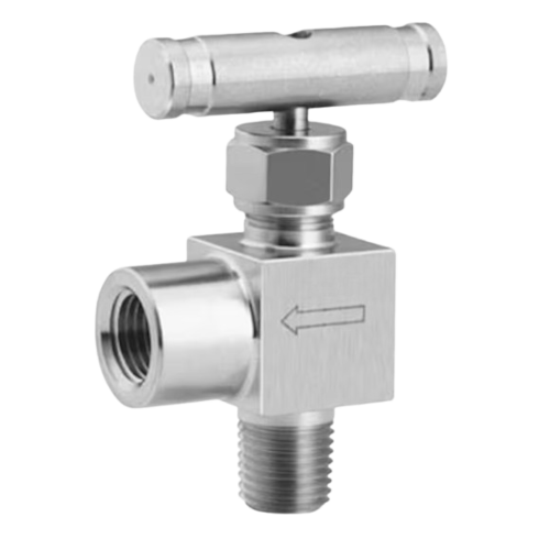
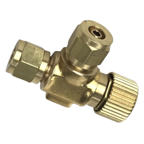
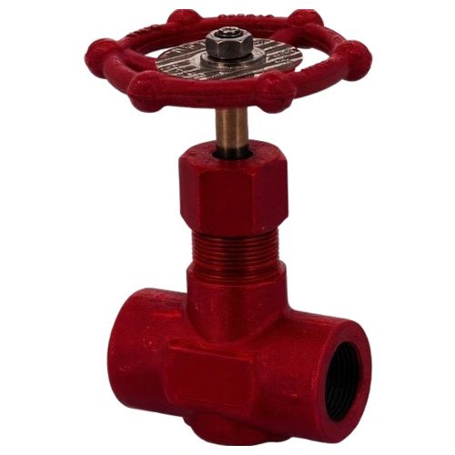
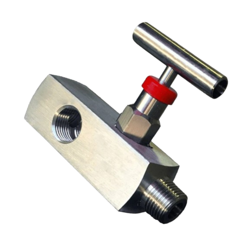
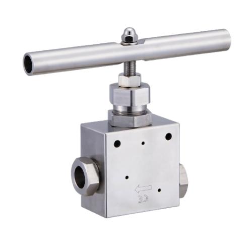
It’s a type of valve that allows for precise control of fluid flow. It consists of a long, tapered needle-like plunger that fits into a matching seat to regulate the flow of fluid. Needle valves are primarily used in situations where small flow rates need to be carefully adjusted, such as in laboratory settings, gas lines, and low-flow applications.
Needle valves are excellent for applications that require fine, precise control over fluid flow, especially in low-flow systems. Their simple design and effectiveness in regulating small amounts of fluid make them ideal for laboratory settings, gas systems, chemical dosing, and instrumentation. While they are not suitable for high-flow conditions and may require maintenance due to wear on the needle and seat, their ability to control flow accurately makes them indispensable in many industries.
Key features of a Needle Valve
-
Precise Flow Control: the most significant feature of a needle valve is its ability to regulate flow with high precision. The needle-like stem moves into the seat, allowing for fine adjustments to control the fluid flow rate.
-
Tapered Needle: has a tapered shape, which allows it to make gradual contact with the valve seat, providing more control over the opening and closing.
-
Handle/Actuation: usually operated manually using a handle or wheel, although there are also automated or actuated versions available for more complex or remote operations.
-
Small Ports: typically feature small ports or orifices, making them suitable for low-flow applications and systems requiring detailed control overflow rates.
Common Applications
- Gas Systems
- Laboratory Equipment
- Chemical Dosing
- Instrumentation
- Oil & Gas Industry
- Hydraulic & Pneumatic Systems
Types of Needle Valves
- Manual Needle Valve
- Automated Needle Valve
- In-Line Needle Valve
- Angle Needle Valve
PLUG VALVE
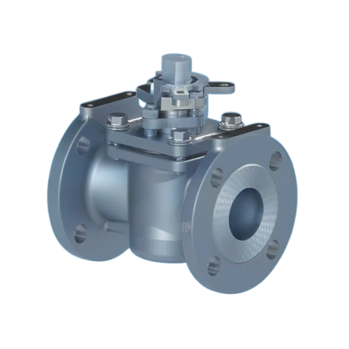
It’s a type of valve that uses a conical or cylindrical plug with a hole (port) through the center to control the flow of fluids. The plug rotates within the valve body to either align or block the flow path.
In summary, a plug valve is a reliable and simple valve that is often used for on/off control or for applications requiring frequent opening and closing.
Key features of a Plug Valve
-
Operation: when the valve handle or actuator is turned, the plug rotates to open or close the flow path. The hole in the plug aligns with the pipe’s flow passage to allow fluid to pass through, and when rotated to a perpendicular position, the hole is blocked, stopping the flow.
-
Design: it can be tapered or cylindrical, and the valve body typically has a seat that ensures a good seal when the valve is closed.
-
Simple Mechanism: are relatively simple, with fewer moving parts, making them reliable for various industrial applications.
Common Applications
- Gas & Oil Systems
- Industrial Plants
- Gas Distribution Systems
- Chemical Processing
- Water Treatment
- Pipeline Systems
- Slurry Transport
Types of Plug Valves
- Lubricated Plug Valve
- Non-Lubricated Plug Vale
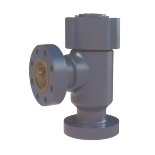
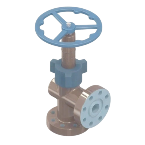
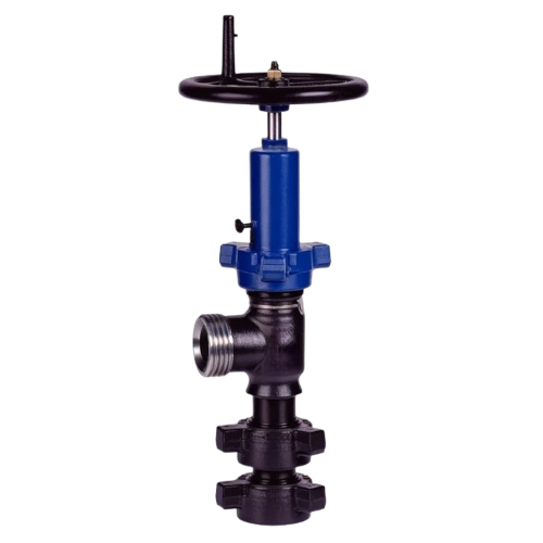
CHOKE VALVE
Choke valves are commonly used in various industries where precise flow control and pressure regulation are critical.
In summary, choke valves are integral to many industries, especially where precise flow control is needed to maintain safety, efficiency, and operational integrity.
Choke valves work by adjusting the size of the opening through which the fluid passes. This adjustment can either increase or decrease the flow rate, and the valve can be manually or automatically controlled. The term “choke” comes from the fact that it “chokes” or restricts the flow of fluid to prevent over-pressurization or excessive flow that could damage equipment or infrastructure.
Key features of a Choke Valve
-
Flow Control: the primary function of a choke valve is to control the flow of fluid (gas, oil, or water) through a pipeline or well. It restricts or regulates the flow by adjusting the size of the opening.
-
Pressure Management: it helps manage pressure by maintaining it within safe operational limits. By controlling the flow rate, they prevent over-pressurization, which could damage equipment or cause hazardous conditions.
-
Adjustability: many choke valves are adjustable, allowing for fine-tuning of the flow rate. This can be done either manually or through automated control systems, depending on the valve’s design.
-
Manual or Automatic Operation: can be operated either manually, using a handwheel or actuator, or automatically through an actuator connected to a control system. Automatic choke valves are often used in systems that require continuous or real-time adjustments.
-
Different types of Design:
- Fixed Choke Valve: the size of the opening is fixed, and the flow rate can only be influenced by external factors, like pressure.
- Adjustable Choke Valve: the size of the opening can be adjusted to vary the flow rate more dynamically.
-
Variable Flow Control: are often used in situations where the flow rate needs to be controlled over time, especially in fields like oil and gas production. The valve can handle varying pressure and flow conditions, offering flexibility in managing different operational scenarios.
-
Material Selection: are made from materials that can withstand harsh conditions, such as high pressures, corrosive environments, or high-temperature applications. Common materials include stainless steel, carbon steel, and alloys that resist wear and corrosion.
-
Safety and Protection: in many industrial applications, choke valves protect sensitive equipment from damage due to high flow rates or pressure surges. They also prevent dangerous situations like blowouts in oil and gas wells by managing flow from the wellhead.
-
Design Variations:
- Positive Choke Valve: typically used to limit the maximum flow rate to a certain level.
- Negative Choke Valve: used for increasing flow or pressure by providing a gradual opening.
-
Durability: are built for long-lasting performance in challenging environments, often requiring minimal maintenance if designed and installed properly.
Common Applications
- Oil & Gas Industry
- Pipeline Flow Regulation
- Pressure Management Systems
- Water & Wastewater Systems
- Chemical processing
- Mining & Mineral Processing
- Power Generation
- Cryogenic Applications
- Steam Systems
- Hydraulic Systems
Types of Choke Valves
- Fixed Choke Valve
- Adjustable Choke Valve
- Positive Choke Valve
- Negative Choke Valve
- Spherical Choke Valve
- Needle Choke Valve
- Dual Choke Valve
- Rotary Choke Valve
- Seat and Plug Choke Valve
- Blowout Preventer (BOP) Choke Valve
- Ventury Choke Valve
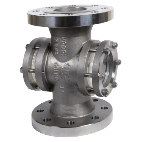
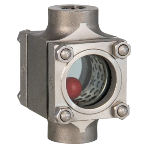
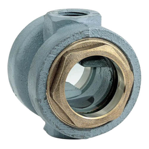
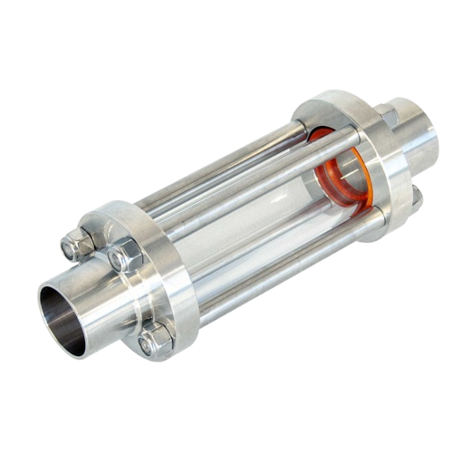
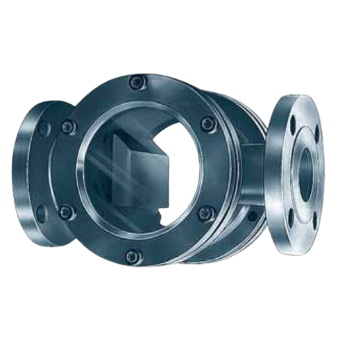
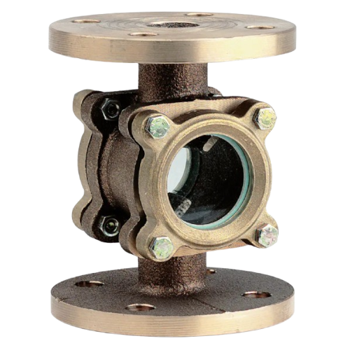
flow indicator
A flow indicator is a device used to visually monitor the flow of a fluid (liquid or gas) within a system. It provides real-time information about the rate of flow, direction of flow, or the presence of flow in pipes, ducts, or other conduits.
Flow indicators are commonly used in industrial applications, such as water treatment plants, oil and gas pipelines, HVAC systems, and chemical processing plants, to ensure that the system is operating correctly and to help identify potential problems like blockages or low flow conditions.
Key features of a Flow Indicator
-
Real-time Monitoring: provide real-time information, helping operators to monitor the flow of fluids in pipelines and systems.
-
Visual Feedback: some flow indicators provide a direct visual indication of flow, which can be useful for operators to quickly assess system performance.
-
Ease of Installation: are generally easy to install and can be incorporated into existing pipeline systems with minimal modifications.
-
Flow Direction: many flow indicators also include arrows or markings to show the correct direction of flow, which is essential for proper operation.
-
Versatility: are used with different types of fluids, including water, air, gases, and various industrial liquids, depending on the material and construction of the indicator.
Common Applications
-
Industrial Process Monitoring
-
Water Treatment
-
HVAC Systems
-
Oil & Gas Industry
-
Food & Beverage
-
Hydraulic Systems
Types of Flow Indicator
-
Mechanical Flow Indicator
-
Electronic Flow Indicators
-
Visual Flow Indicators
Actuators
An actuator is a device used to control a mechanism or system by converting a form of energy into mechanical motion. Actuators play a fundamental role in modern mechanical systems by converting different forms of energy into motion.
Whether using electricity, compressed air, hydraulic fluid, or thermal energy, actuators are vital in industries ranging from manufacturing to aerospace.
By selecting the appropriate actuator for each application, businesses can ensure efficient and reliable performance of their systems, contributing to smoother operations and higher productivity.
The main functions of an Actuator
- Precision: provide precise control over mechanical motion, which is crucial in applications like robotics and automated manufacturing.
- Speed and Force Control: can be designed to produce high-speed or high-force movements, depending on the needs of the system. For example, hydraulic actuators are often used when high force is required.
- Reliability: are built to withstand extreme conditions, such as high temperatures, pressures, or hazardous environments, depending on the type of actuator.
- Durability: are designed for longevity and can often operate for long periods before requiring maintenance or replacement.
- Adaptability: are versatile and can be tailored to meet the needs of specific systems, whether that’s with a linear or rotary motion, or the use of electrical, pneumatic, hydraulic, or mechanical force.
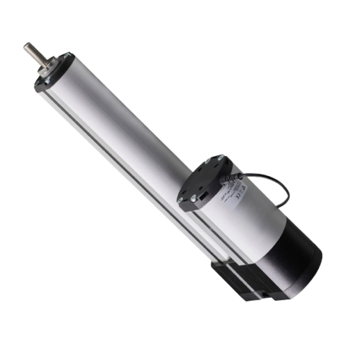
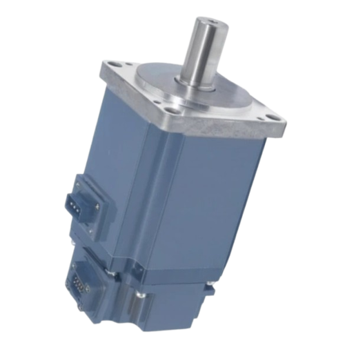
electric actuator
An electric actuator is a device that converts electrical energy into mechanical motion.
It is typically used in applications where precise control over movement is required, such as in robotics, industrial automation, HVAC systems, and various other machinery.
Electric actuators are known for their accuracy, reliability, and ease of integration with control systems, making them a popular choice for modern automation and control processes.
Key features of an Electric Actuator
-
Power Source: are powered by electricity (AC or DC), as opposed to pneumatic or hydraulic actuators that use air or fluid pressure. Suitable for applications where a stable and controllable power source is available.
-
Precision and Control: offer precise control over the movement of mechanical components. The movement can be fine-tuned to exact specifications, making them ideal for applications requiring high accuracy. Many come with speed controls, allowing for adjustable movement speeds depending on the application needs.
-
Torque Output: provide consistent torque over the full range of their travel. Designed to handle varying loads, ensuring that the output is sufficient to perform the intended task (opening a valve or moving a robotic arm).
-
Easy integration with Control Systems: can be easily integrated into automation systems, as they can be controlled using standard electrical signals (like 4-20mA, 0-10V, or digital protocols such as Modbus, Profibus, or BACnet) can be controlled remotely using a controller or a programmable logic controller (PLC), which is a significant advantage in industrial automation.
-
Accuracy in Positioning: can be used for a variety of tasks, valve control, gate operation, damper control, and robotic movements. Used in industries such as water treatment, chemical processing, automotive manufacturing, and more.
-
Compact Design: are often compact, especially compared to pneumatic or hydraulic actuators. Their size and design make them suitable for applications where space is limited: robotics or small-scale machinery.
-
Energy Efficiency: are energy-efficient compared to pneumatic or hydraulic actuators in many cases, as they do not require external compressors or pumps. They also offer better energy usage by only consuming power when required, resulting in less waste and lower operational costs.
-
Safety Features: many electric actuators include built-in safety features – overload protection, which prevents damage to the actuator or the connected machinery. In some models, the actuator can be designed to fail in a safe position in case of power loss or malfunction, such as returning to a default or fail-safe position.
-
Maintenance and Durability: generally, require less maintenance compared to pneumatic or hydraulic actuators, as they have fewer moving parts and don’t rely on external systems like air compressors or fluid pumps. With proper use and maintenance, electric actuators are durable and can last for many years without significant wear or failure.
-
Noise Level: are often quieter than pneumatic or hydraulic actuators, which is particularly beneficial in noise-sensitive environments (e.g., hospitals, offices, or residential areas).
-
Environmental Adaptability: can be designed to operate in harsh environments, including extreme temperatures, humidity, or hazardous locations, depending on the materials and seals used. Special types of electric actuators are rated for use in explosion-proof environments.
-
Cost: while the initial cost of electric actuators can be higher than some other types (e.g., pneumatic actuators), their long-term energy efficiency, low maintenance, and precision can make them cost-effective over time.
-
Customization: are available in various sizes, torque capacities, and stroke lengths, allowing for customization based on the specific requirements of the application. Whether it’s for small-scale operations or heavy-duty tasks, electric actuators can be tailored to fit the job.
Common Applications
- Aerospace & Aviation
- Entertainment & Theme Parks
- Robotics & Automation
- Positioning Systems
- Gate & Door Automation
- Automotive Industry
- Theater & Stage Productions
- Pulp & Paper Industry
- Food & Beverage Industry
- Water Treatment Plants
- Packaging Industry
- Agriculture & Farming
- Valve Control
- Medical Equipment
- Industrial Equipment
- HVAC Systems
- Energy Sector
Types of Electric Actuators
- Linear Electric Actuators
- Rotary Electric Actuators
- Servo Motors
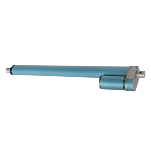
hydraulic actuator
A hydraulic actuator uses pressurized hydraulic fluid (usually oil) to create mechanical motion. This energy is converted into either linear or rotary motion to perform tasks such as controlling machinery, valves, or other mechanical systems. Hydraulic actuators are commonly used in heavy-duty applications where high force and precision are required, such as in construction equipment, industrial machinery, aerospace, and automotive systems.
A hydraulic actuator is a powerful and precise device that uses pressurized hydraulic fluid to generate mechanical motion. Although they provide significant benefits in terms of force and control, hydraulic actuators come with challenges such as complexity, fluid leaks, and energy consumption that must be carefully managed.
Key features of an Hydraulic Actuator
-
High Force Output: can generate very high forces due to the incompressibility of the hydraulic fluid. This makes them suitable for heavy-duty applications where electric or pneumatic actuators might not be able to produce sufficient force.
-
Precision: can offer precise control over motion, particularly in situations requiring high torque or force, such as in heavy machinery or aerospace applications.
-
Compact and Strong: can achieve significant force in a relatively compact size, which is advantageous in applications where space is limited but high power is required.
-
Energy Density: can operate in confined spaces and perform tasks requiring a lot of power because hydraulic fluid has high energy density, meaning smaller components can still produce significant amounts of force.
-
Continuous Operation: can work continuously, offering sustained operation without overheating, if the hydraulic fluid is properly managed and maintained.
Common Applications
- Construction & Heavy Equipment
- Automotive Industry
- Industrial Manufacturing
- Marine & Offshore
- Aerospace
- Mining & Extraction
- Agricultural Machinery
Types of Hydraulic Actuators
-
Linear Hydraulic Actuators
-
Rotary Hydraulic Actuators
Pneumatic actuator
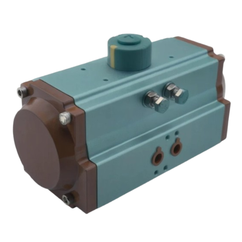
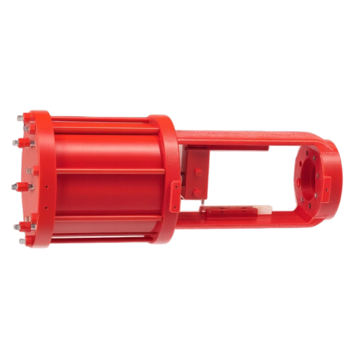
A pneumatic actuator is a type of actuator that uses compressed air or gas to generate mechanical motion. It converts the energy from compressed air into linear or rotary motion, enabling the actuation of mechanical systems, such as valves, dampers, and other equipment in industrial applications.
Pneumatic actuators are commonly used in automated systems and are known for their speed, reliability, and simplicity. They are especially useful in environments where electric actuators might pose risks (such as in explosive environments) or when the application requires fast actuation cycles.
Key features of a Pneumatic Actuator
-
Speed: are known for their high speed. Compressed air provides quick actuation, making them ideal for fast response times in applications like automated machinery.
-
High Force Output: with proper sizing, pneumatic actuators can generate a substantial amount of force, making them suitable for heavy-duty applications.
-
Simplicity: they have relatively simple designs and are easy to operate, requiring minimal maintenance compared to other types of actuators.
-
Reliability: are robust and reliable, especially in harsh environments where electrical actuators might be vulnerable to failure due to moisture, dust, or other contaminants.
-
Environmentally Safe: since they operate on compressed air, pneumatic actuators do not require oil or other potentially hazardous fluids, making them a cleaner choice for certain environments.
Common Applications
- Valve Actuation
- Packaging Machines
- Robotics
- Manufacturing & Assembly
- Transportation Systems
Types of Pneumatic Actuators
- Linear Pneumatic Actuators
- Rotary Pneumatic Actuators
Gearboxes
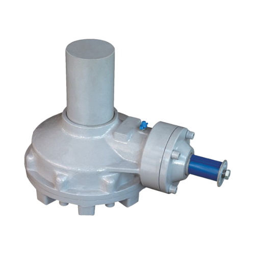
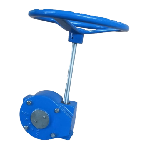
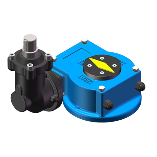
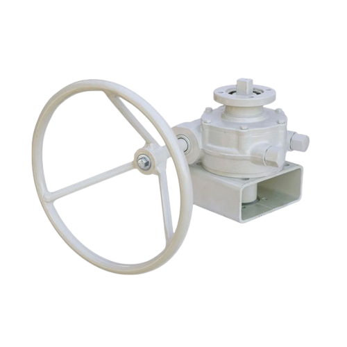
Manual Gearbox
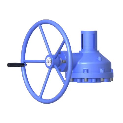
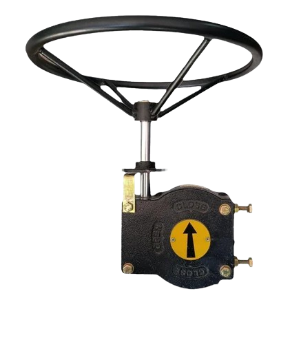
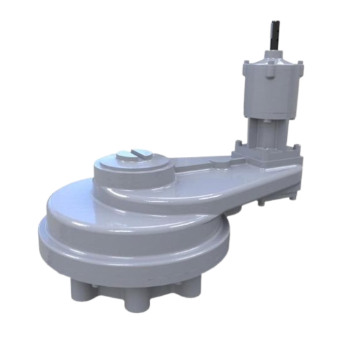
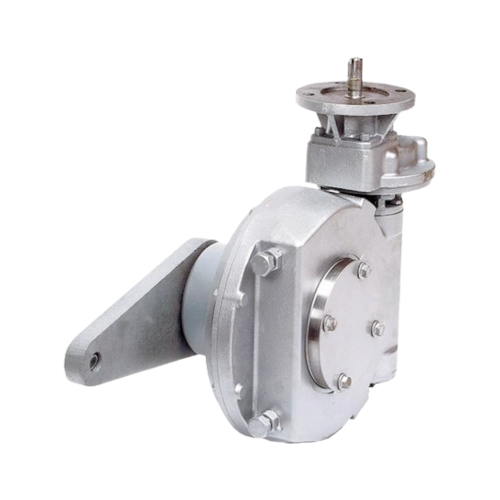
A manual valve gearbox is a mechanical device used to control the operation of a valve, especially in industrial and process control systems, where precise control over the valve’s position is required. It is essentially a gearbox that operates manually to adjust the valve’s opening or closing.
The manual valve gearbox is typically attached to a valve’s stem and allows the operator to turn a handwheel or lever to change the valve’s position. The gearbox provides mechanical advantage to reduce the torque needed to operate the valve, making it easier to turn, particularly for large or heavy valves.
Common components:
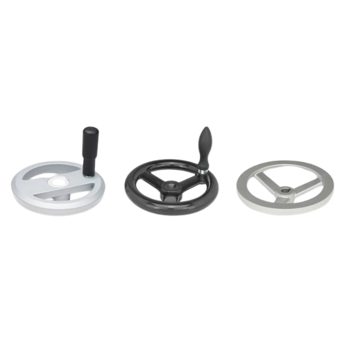
- Handwheel or Lever: the operator uses these to manually turn the valve
- Gear Mechanism: this helps to reduce the amount of manual effort needed to turn the valve.
- Stem Connection: the gearbox is connected to the valve stem, which moves to adjust the valve.
Overall, a manual valve gearbox makes valve operation more efficient and controlled, particularly in settings where valves need to be adjusted by hand rather than automatically or remotely.
Key features of a Gearbox
-
Torque reduction: the gearbox reduces the amount of force needed to turn the valve, especially in cases where high torque is required to move the valve.
-
Precise control: it provides precise control over the valve’s position, which is crucial in systems where exact flow control is needed (e.g., in pipelines, pressure systems, or fluid handling).
-
Manual Operation: it allows operators to manually adjust the valve, which is especially important in situations where automatic valve control is not available or desired.
-
Durability: manual valve gearboxes are often built to withstand harsh environments, including extreme temperatures, pressure, or corrosive conditions.
Common Applications
- Oil & Gas
- Water Treatment
- Power Plants
- Chemical Plants
Types of Gearboxes
-
Bevel Gearbox
-
Large Bevel Gearbox
-
Helical Gearbox
-
Multi-turn Gearbox
-
Part-turn Gearbox
-
Planetary Gearbox
-
Quarter-turn Gearbox
-
Spur Gearbox
-
Lever Arm for Dampers
Gearboxes Accessories
-
Lever Arm for Dampers
-
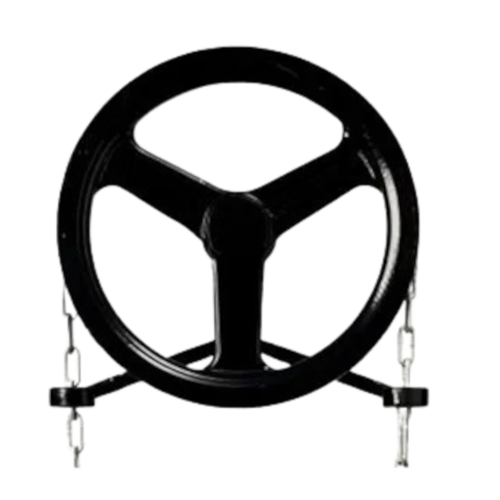
Hand Wheels
-
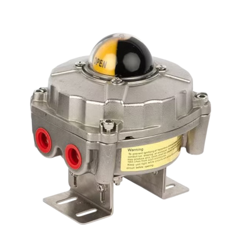
Position Indicator / Switches
-
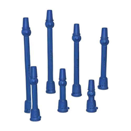
Extension Spindles
-
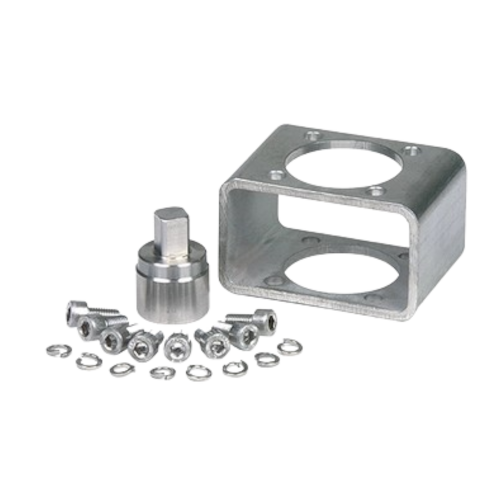
Mounting Kit
Information request
Enter your details in the form below to request information on our products and services.
"*" indica i campi obbligatori
